Arduino controlled photogrammetry 3D-scanner


DESCRIPTION
DETAILS
As said before this turntable is a new and improved version of my hand cranked version. A lot of people suggested to me I should put a stepper motor onto it to get some very nice cinematic shots. This is exactly what I did.
I gave it a bit more functionality than just a regular cinematic turntable. I added the possibility to use the turntable to capture photos 360 degrees around an object.
The photos are being taken by a smartphone connected to a Bluetooth remote located inside the turntable. I just used the most straight forward, obvious and simple solution to capture these photos, which was to use a servo to press a button on a Bluetooth remote. I went for this solution due to the fact that Apple products tend to not like the HC-05 and HC-06 Bluetooth modules and refuse to connect to them. I’m sure a cleaner and more durable solution is to use these HC-05 or HC-06 modules and connect them to an android device.
The amount of photo's that have to be taken can be determined by the user, ranging from 2 photo's to 200 photo's. These values can be easily adjusted in the Arduino program. The taken photos can be converted later on into a 3D-model using photogrammetry software. The photogrammetry software I use is Autodesk Recap Photo.
In the second menu you can find the possibility to use the turntable to make awesome cinematic shots of your objects. In this mode the turntable rotates a certain amount of turns at a constant speed chosen by the user ranging from 1 to 17 RPM (speed of the stepper motor).
The third and last menu enables the user to manually control the turntable and bring the plate to the desired position at the preferred speed.
All the mechanical parts of this turntable are completely 3D-printed. The bearing for example is a print-in-place one which works great for this application. The print in place of moving objects adds to the simplicity of the build.
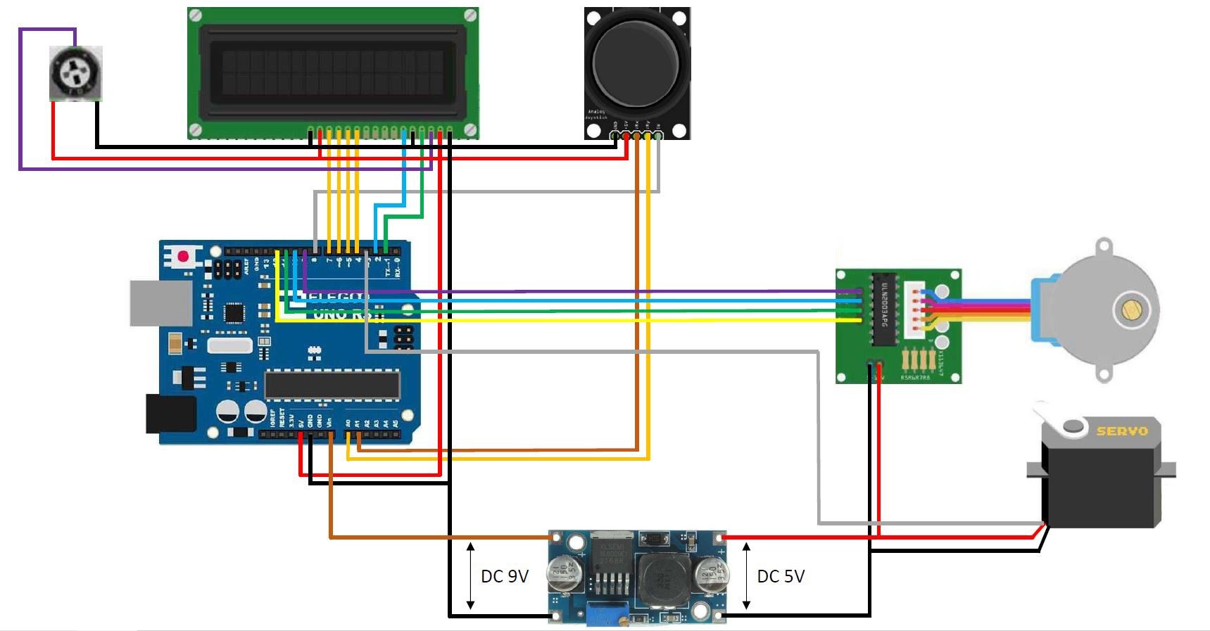
The reason I didn't connect the servo and stepper motor to the onboard 5V regulator and used an extra buck converter is because the stepper motor and servo draw to much current. Every time the stepper motor rotated or stopped, the backlight in the LCD got brighter and dimmer due to the fluctuation in voltage. Using an extra buck converter takes the load from the 5 volt onboard regulator.
Video:
FILES
STL-files and the Fusion 360 source files can be downloaded here: https://bbprojects.technology/stl-fusion-360-source-files/arduino-controlled-photogrammetry-3d-scanner-files
Arduino code can be downloaded here
Wiring diagram can be downloaded here
COMPONENTS
| QUANTITY | COMPONENT NAME | |
| 1 | × | 9g Servo motor link: http://www.amazon.nl/dp/B07MY2Y253/ref=nosim?tag=bbrocken-21 |
| 1 | × | 1602 blue LCD-screen link: http://www.amazon.nl/dp/B0B1TZMZQY/ref=nosim?tag=bbrocken-21 |
| 2 | × | 4.0X16mm wood screw These are being used to secure the stepper motor in place |
| 2 | × | 3.0X12mm wood screw cut to 5mm lenghtThese screws are being used to secure the arduino nano in place. |
| 1 | × | Arduino uno link: http://www.amazon.nl/dp/B01MDJA464/ref=nosim?tag=bbrocken-21 |
| 1 | × | Double sided prototype board 4cmX6cm link: http://www.amazon.nl/dp/B0734XYJPM/ref=nosim?tag=bbrocken-21 |
| 1 | × | DC-DC step down regulator link: http://www.amazon.nl/dp/B07MY2NTFV/ref=nosim?tag=bbrocken-21 |
| 1 | × | Joystick link: http://www.amazon.nl/dp/B07V3HQSVY/ref=nosim?tag=bbrocken-21 |
| 1 | × | stepper motor and driver link: http://www.amazon.nl/dp/B09Z27VDHJ/ref=nosim?tag=bbrocken-21 |
| 1 | × | Bluetooth remote link: http://www.amazon.nl/dp/B07MHZRDV9/ref=nosim?tag=bbrocken-21 |
| 1 | × |
10K potentiometer: Please note the linked one is not the same I used in my scanner. The one I used was part of an arduino kit and I couldn't find the same one online. But since you only need to adjust the value of the potentiometer once to adjust the brightness of the display, the potentiometers in the link will work just fine: http://www.amazon.nl/dp/B07DJ59V8Z/ref=nosim?tag=bbrocken-21 |
PROJECT LOGS
-
Added a code contribution from Ryan Hashiro to the files section
09/20/2020 at 19:37Added a code contribution from Ryan Hashiro to the files section on this page.
-
Added a YouTube video to the details section of this page
09/20/2020 at 19:34
-
Voltage Distributor
04/23/2020 at 09:44At around 3:15 in the video (https://youtu.be/SAgiv4o8rxQ) you can see I'm installing a little part next to the Arduino Uno. This is a homemade voltage distributor. It's sole purpose is to distribute 5V and 0V to other components. I made it using some double sided prototype board and soldering some 2.54mm female header pins on it. All the 5V pins are soldered together and all the 0V pins are soldered together, just like the + and - strips on a breadbord (see green box on picture below). Hope this cleared it out for some people.
Double sided prototype boards: https://www.banggood.com/Geekcreit-40pcs-FR-4-2_54mm-Double-Side-Prototype-PCB-Printed-Circuit-Board-p-995732.html?p=E01411629100201406T1&custlinkid=669188
2.54mm female header pins: https://www.banggood.com/10pcs-40Pin-2_54mm-Female-Header-Connector-Socket-For-DIY-Arduino-p-945516.html?rmmds=search&cur_warehouse=CN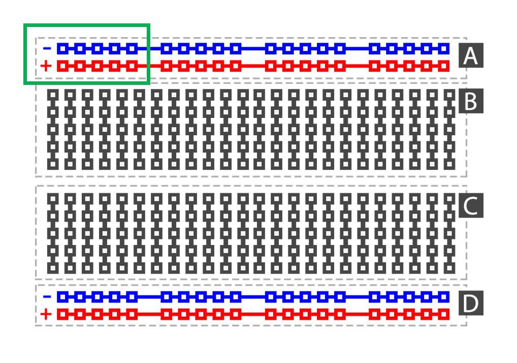
-
Updated wiring diagram
11/24/2019 at 20:17Made a very small adjustment in the wiring diagram to avoid possible confusion with the 5V and Vin pin. I changed the color of the Vin wire to orange, the 5V and Vin wire should not be connected together. The 5V wire goes up to the LCD, joystick and potentiometer. The Vin wire goes to the DC-DC step down voltage regulator.
-
Arduino code added to the files section
11/06/2019 at 11:54
-
Added a wiring diagram to the files section
11/05/2019 at 21:05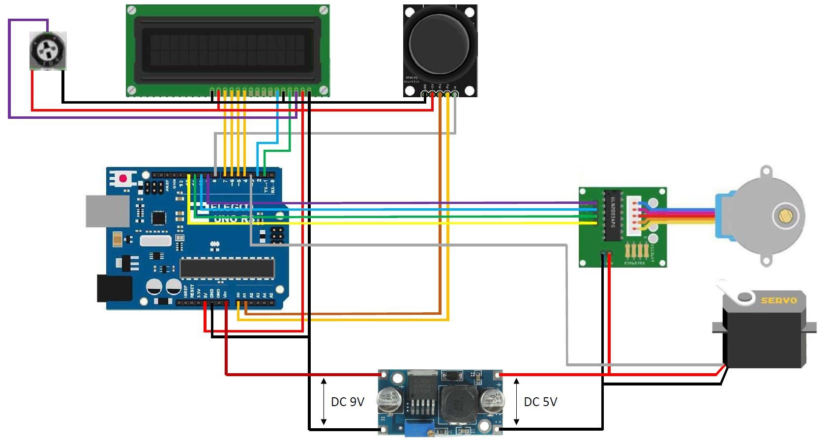
DETAILS
As said before this turntable is a new and improved version of my hand cranked version. A lot of people suggested to me I should put a stepper motor onto it to get some very nice cinematic shots. This is exactly what I did.
I gave it a bit more functionality than just a regular cinematic turntable. I added the possibility to use the turntable to capture photos 360 degrees around an object.
The photos are being taken by a smartphone connected to a Bluetooth remote located inside the turntable. I just used the most straight forward, obvious and simple solution to capture these photos, which was to use a servo to press a button on a Bluetooth remote. I went for this solution due to the fact that Apple products tend to not like the HC-05 and HC-06 Bluetooth modules and refuse to connect to them. I’m sure a cleaner and more durable solution is to use these HC-05 or HC-06 modules and connect them to an android device.
The amount of photo's that have to be taken can be determined by the user, ranging from 2 photo's to 200 photo's. These values can be easily adjusted in the Arduino program. The taken photos can be converted later on into a 3D-model using photogrammetry software. The photogrammetry software I use is Autodesk Recap Photo.
In the second menu you can find the possibility to use the turntable to make awesome cinematic shots of your objects. In this mode the turntable rotates a certain amount of turns at a constant speed chosen by the user ranging from 1 to 17 RPM (speed of the stepper motor).
The third and last menu enables the user to manually control the turntable and bring the plate to the desired position at the preferred speed.
All the mechanical parts of this turntable are completely 3D-printed. The bearing for example is a print-in-place one which works great for this application. The print in place of moving objects adds to the simplicity of the build.
The reason I didn't connect the servo and stepper motor to the onboard 5V regulator and used an extra buck converter is because the stepper motor and servo draw to much current. Every time the stepper motor rotated or stopped, the backlight in the LCD got brighter and dimmer due to the fluctuation in voltage. Using an extra buck converter takes the load from the 5 volt onboard regulator.
Video:
FILES
STL-files and the Fusion 360 source files can be downloaded here: https://bbprojects.technology/stl-fusion-360-source-files/arduino-controlled-photogrammetry-3d-scanner-files
Arduino code can be downloaded here
Wiring diagram can be downloaded here
COMPONENTS
PROJECT LOGS
-
Added a code contribution from Ryan Hashiro to the files section
09/20/2020 at 19:37Added a code contribution from Ryan Hashiro to the files section on this page.
-
Added a YouTube video to the details section of this page
09/20/2020 at 19:34
-
Voltage Distributor
04/23/2020 at 09:44At around 3:15 in the video (https://youtu.be/SAgiv4o8rxQ) you can see I'm installing a little part next to the Arduino Uno. This is a homemade voltage distributor. It's sole purpose is to distribute 5V and 0V to other components. I made it using some double sided prototype board and soldering some 2.54mm female header pins on it. All the 5V pins are soldered together and all the 0V pins are soldered together, just like the + and - strips on a breadbord (see green box on picture below). Hope this cleared it out for some people.
Double sided prototype boards: https://www.banggood.com/Geekcreit-40pcs-FR-4-2_54mm-Double-Side-Prototype-PCB-Printed-Circuit-Board-p-995732.html?p=E01411629100201406T1&custlinkid=669188
2.54mm female header pins: https://www.banggood.com/10pcs-40Pin-2_54mm-Female-Header-Connector-Socket-For-DIY-Arduino-p-945516.html?rmmds=search&cur_warehouse=CN -
Updated wiring diagram
11/24/2019 at 20:17Made a very small adjustment in the wiring diagram to avoid possible confusion with the 5V and Vin pin. I changed the color of the Vin wire to orange, the 5V and Vin wire should not be connected together. The 5V wire goes up to the LCD, joystick and potentiometer. The Vin wire goes to the DC-DC step down voltage regulator.
-
Arduino code added to the files section
11/06/2019 at 11:54 -
Added a wiring diagram to the files section
11/05/2019 at 21:05
DETAILS
As said before this turntable is a new and improved version of my hand cranked version. A lot of people suggested to me I should put a stepper motor onto it to get some very nice cinematic shots. This is exactly what I did.
I gave it a bit more functionality than just a regular cinematic turntable. I added the possibility to use the turntable to capture photos 360 degrees around an object.
The photos are being taken by a smartphone connected to a Bluetooth remote located inside the turntable. I just used the most straight forward, obvious and simple solution to capture these photos, which was to use a servo to press a button on a Bluetooth remote. I went for this solution due to the fact that Apple products tend to not like the HC-05 and HC-06 Bluetooth modules and refuse to connect to them. I’m sure a cleaner and more durable solution is to use these HC-05 or HC-06 modules and connect them to an android device.
The amount of photo's that have to be taken can be determined by the user, ranging from 2 photo's to 200 photo's. These values can be easily adjusted in the Arduino program. The taken photos can be converted later on into a 3D-model using photogrammetry software. The photogrammetry software I use is Autodesk Recap Photo.
In the second menu you can find the possibility to use the turntable to make awesome cinematic shots of your objects. In this mode the turntable rotates a certain amount of turns at a constant speed chosen by the user ranging from 1 to 17 RPM (speed of the stepper motor).
The third and last menu enables the user to manually control the turntable and bring the plate to the desired position at the preferred speed.
All the mechanical parts of this turntable are completely 3D-printed. The bearing for example is a print-in-place one which works great for this application. The print in place of moving objects adds to the simplicity of the build.
The reason I didn't connect the servo and stepper motor to the onboard 5V regulator and used an extra buck converter is because the stepper motor and servo draw to much current. Every time the stepper motor rotated or stopped, the backlight in the LCD got brighter and dimmer due to the fluctuation in voltage. Using an extra buck converter takes the load from the 5 volt onboard regulator.
Video:
FILES
STL-files and the Fusion 360 source files can be downloaded here: https://bbprojects.technology/stl-fusion-360-source-files/arduino-controlled-photogrammetry-3d-scanner-files
Arduino code can be downloaded here
Wiring diagram can be downloaded here
COMPONENTS
| QUANTITY | COMPONENT NAME | ||
| 1 | × | 9g Servo motor link:
|
|
| 1 | × | 1602 blue LCD-screen link: https://www.banggood.com/Geekcreit-IIC-I2C-1602-Blue-Backlight-LCD-Display-Screen-Module-For-Arduino-p-950726.html?p=E01411629100201406T1&custlinkid=669170 | |
| 2 | × | 4.0X16mm wood screwThese are being used to secure the stepper motor in place | |
| 2 | × | 3.0X12mm wood screw cut to 5mm lenghtThese screws are being used to secure the arduino nano in place. | |
| 1 | × | Arduino uno link: https://www.banggood.com/Wholesale-Arduino-Compatible-R3-UNO-ATmega16U2-AVR-USB-Board-p-68537.html?p=E01411629100201406T1&custlinkid=669183 | |
| 1 | × | Double sided prototype board 4cmX6cm type: 107822J2H link: https://www.banggood.com/Geekcreit-40pcs-FR-4-2_54mm-Double-Side-Prototype-PCB-Printed-Circuit-Board-p-995732.html?p=E01411629100201406T1&custlinkid=669188 | |
| 1 | × | DC-DC step down regulator link: https://www.banggood.com/LM2596-DC-DC-Verstellbar-Step-Down-Schaltregler-Power-Supply-Module-p-88252.html?p=E01411629100201406T1&custlinkid=255154 | |
| 1 | × | Joystick link: https://www.banggood.com/JoyStick-Module-Shield-2_54mm-5-pin-Biaxial-Buttons-Rocker-for-PS2-Joystick-Game-Controller-Sensor-For-Arduino-p-1566502.html?rmmds=search&cur_warehouse=CN | |
| 1 | × | stepper motor and driver link: https://www.banggood.com/28YBJ-48-DC-5V-4-Phase-5-Wire-Stepper-Motor-With-ULN2003-Driver-Board-p-74397.html?rmmds=search&cur_warehouse=CN | |
| 1 | × | Bluetooth remote link: https://www.banggood.com/Multifunctional-Bluetooth-Remote-Control-Gamepad-For-BlitzWolf-VR-Glasses-p-1041787.html?rmmds=search&cur_warehouse=CN | |
| 1 | × | 10K potentiometer: Please note the linked one is not the same I used in my scanner. The one I used was part of an arduino kit and I couldn't find the same one online. But since you only need to adjust the value of the potentiometer once, the potentiometers in the link work just fine: https://www.banggood.com/20pcs-RM065-10K-Ohm-Trimpot-Trimmer-Potentiometer-Variable-Resistor-p-1465829.html?rmmds=search&cur_warehouse=CN |
PROJECT LOGS
-
Added a code contribution from Ryan Hashiro to the files section
09/20/2020 at 19:37Added a code contribution from Ryan Hashiro to the files section on this page.
-
Added a YouTube video to the details section of this page
09/20/2020 at 19:34
-
Voltage Distributor
04/23/2020 at 09:44At around 3:15 in the video (https://youtu.be/SAgiv4o8rxQ) you can see I'm installing a little part next to the Arduino Uno. This is a homemade voltage distributor. It's sole purpose is to distribute 5V and 0V to other components. I made it using some double sided prototype board and soldering some 2.54mm female header pins on it. All the 5V pins are soldered together and all the 0V pins are soldered together, just like the + and - strips on a breadbord (see green box on picture below). Hope this cleared it out for some people.
Double sided prototype boards: https://www.banggood.com/Geekcreit-40pcs-FR-4-2_54mm-Double-Side-Prototype-PCB-Printed-Circuit-Board-p-995732.html?p=E01411629100201406T1&custlinkid=669188
2.54mm female header pins: https://www.banggood.com/10pcs-40Pin-2_54mm-Female-Header-Connector-Socket-For-DIY-Arduino-p-945516.html?rmmds=search&cur_warehouse=CN -
Updated wiring diagram
11/24/2019 at 20:17Made a very small adjustment in the wiring diagram to avoid possible confusion with the 5V and Vin pin. I changed the color of the Vin wire to orange, the 5V and Vin wire should not be connected together. The 5V wire goes up to the LCD, joystick and potentiometer. The Vin wire goes to the DC-DC step down voltage regulator.
-
Arduino code added to the files section
11/06/2019 at 11:54 -
Added a wiring diagram to the files section
11/05/2019 at 21:05
Realice el proyecto, e investigando encontré esta pagina (https://www.instructables.com/Control-Phone-Camera-Wirelessly-Using-ARDUINO/) donde que me pareció interesante simplificar el hardware suprimiendo el servomotor por un transistor npn que en mi caso utilice un 2N 3904 y parte del código de esta pagina fue anexado al código de ustedes teniendo las dos posibilidades de usar el servo tocando el pulsador o el transistor cerrando el circuito y que no haya un desgaste o falla mecánica.
Cordial Saludo, Me gusto el proyecto el cual ya me ensamble uno para mi, encontré esta pagina (https://www.instructables.com/Control-Phone-Camera-Wirelessly-Using-ARDUINO/) que me pareció interesante y el cual tome parte del código de el y lo añadí al suyo dejando las dos opciones la del servomotor y la del transistor el cual suprime al servo convirtiéndose en un interruptor haciendo mas limpio el trabajo de tomar las fotos y menos desgaste mecánico.