Building a full scale flying Delorean


DESCRIPTION
DETAILS
First flight of the full-scale flying delorean (19/09/2025)
Just posted a new video of the first flight of the full scale DeLorean on Youtube:
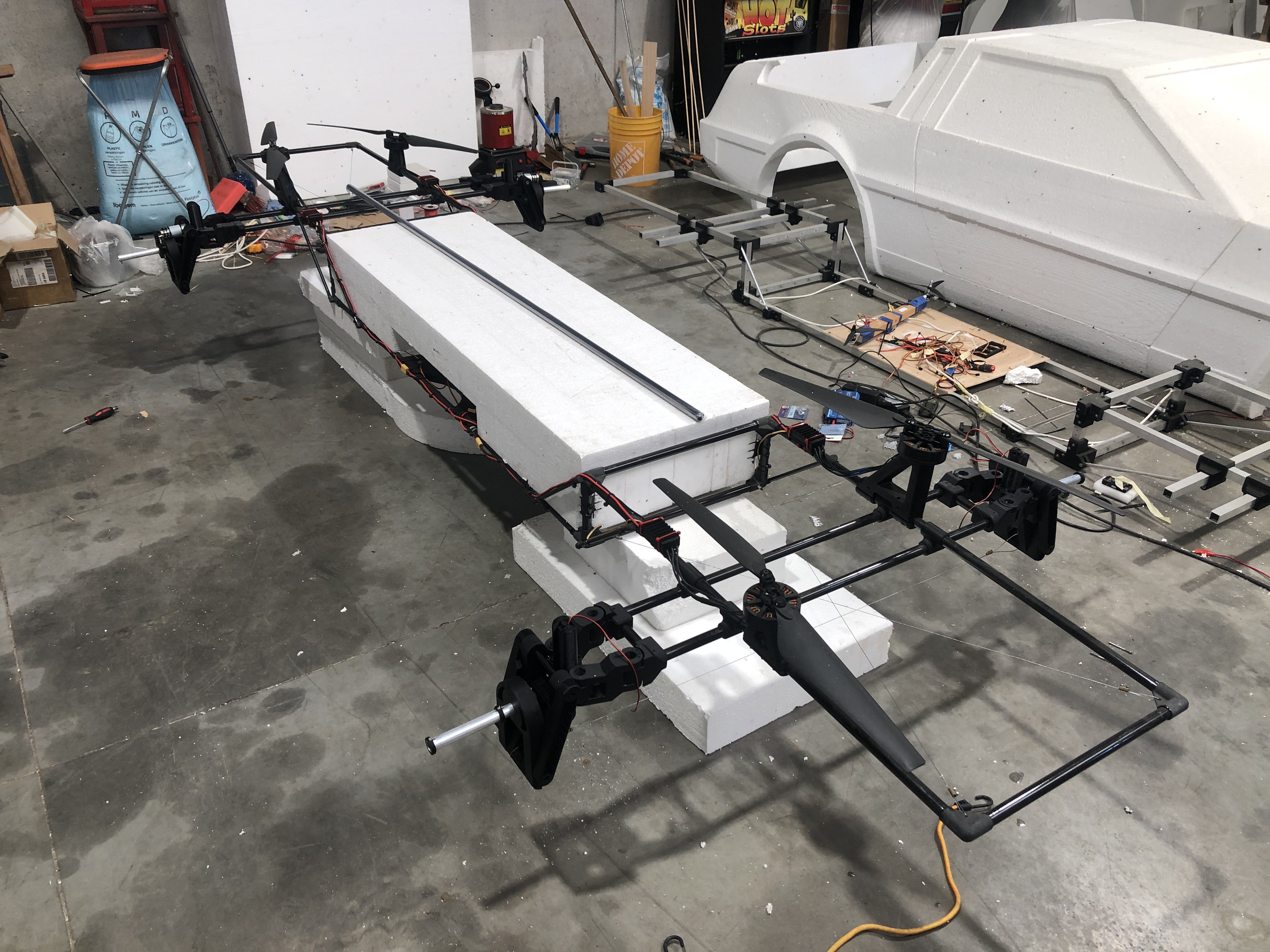
New Carbon fiber airframe
The original aluminium airframe was to heavy and not ridgid enough because of the 3D-printed parts. There was only 1 material I could think of that would be light and sturdy enough for this application which is: Carbon Fiber.
I designed a tubular frame that would be held together with "forged carbon fiber" corners. The "forged carbon fiber" corners (It's technically not forged but i have no other way of naming it) are made using 3D-printed molds which are filled with loose fibers, combined with a resin and then pressed together with clamps.
The carbon fiber tubes and corners are held together with the same resin I used to make the corners with.
After the frame was assembled, i added extra diagonal steel wires to reduce the remaining torsion in the frame.
I also used a large foam EPS block in between the drone to simulate the EPS foam DeLorean body (and to add extra ridgidity to the drone frame during test flights).
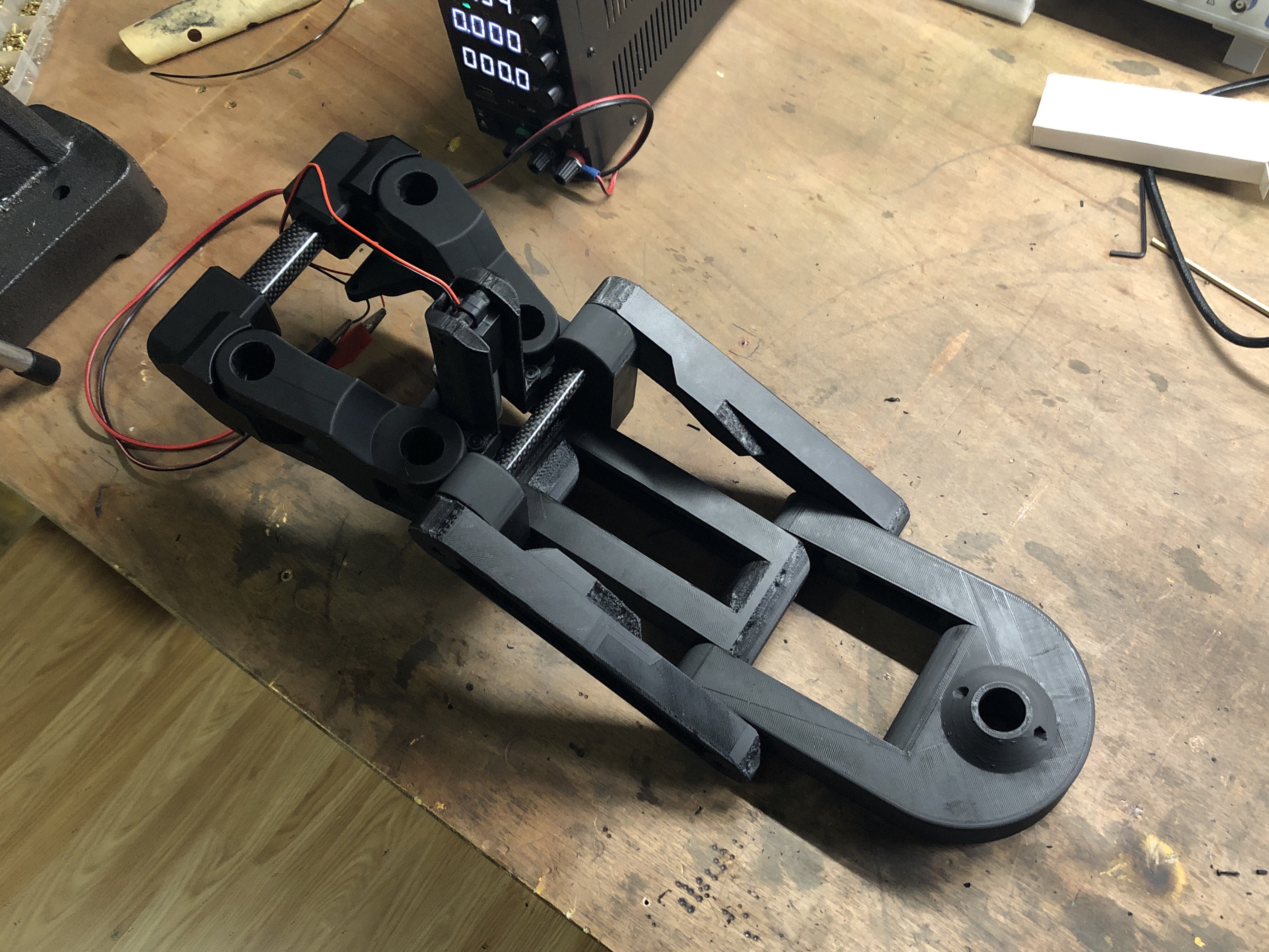
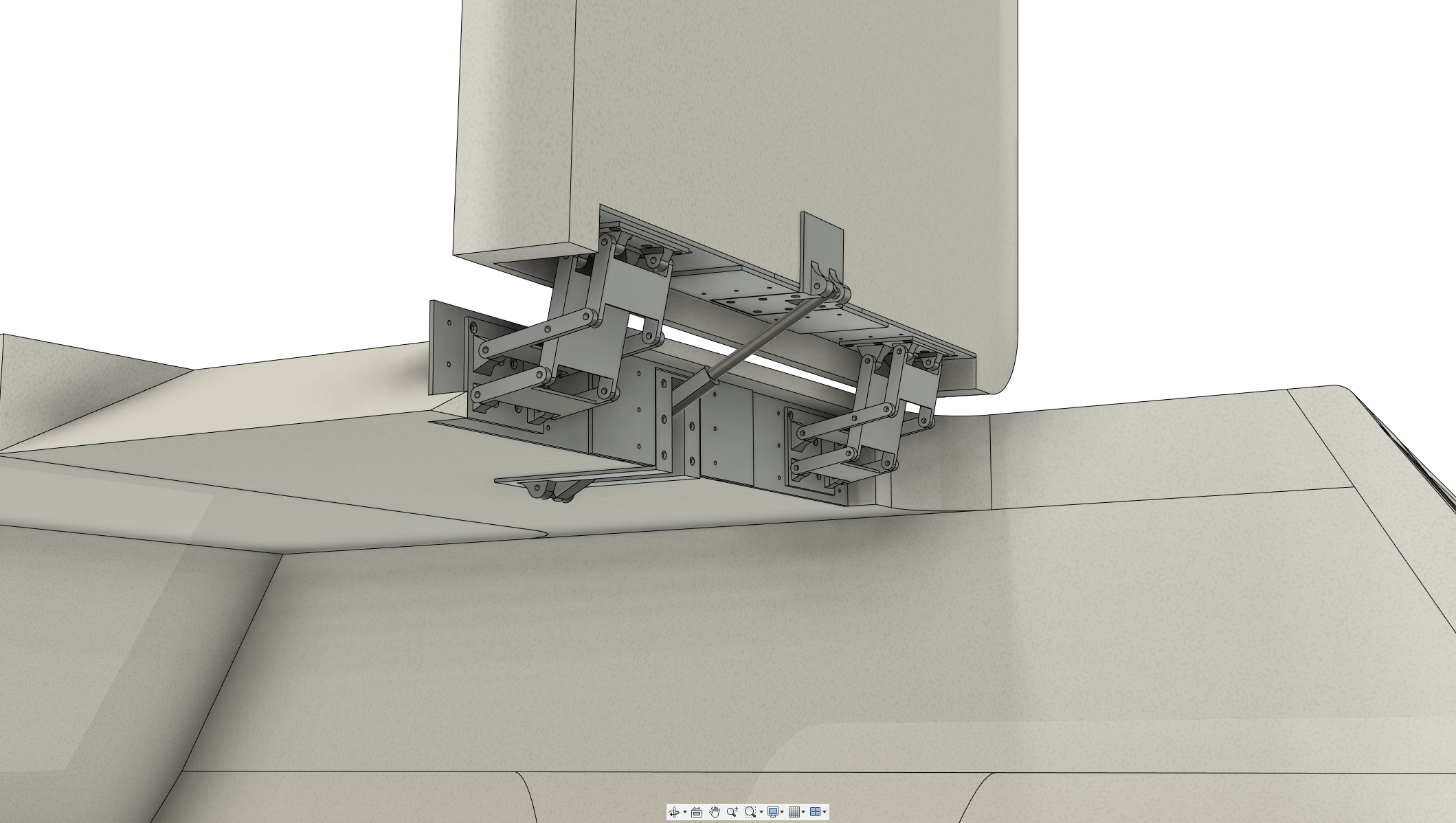
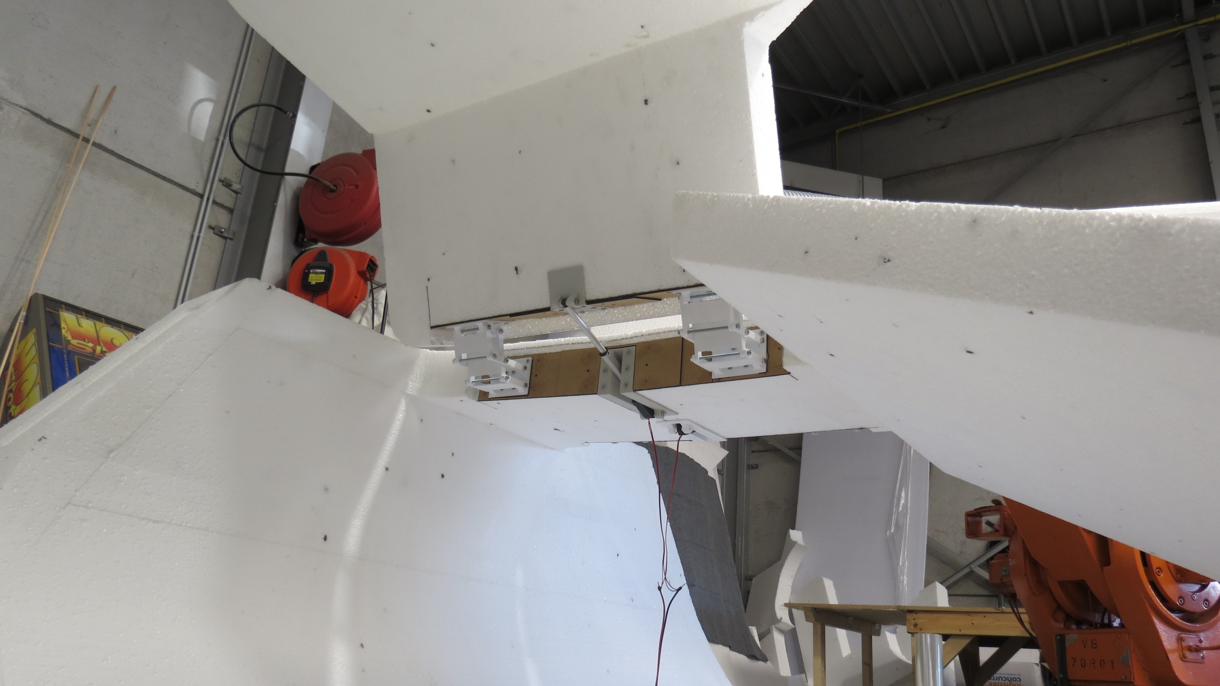
Wheel retract, steering and driving mechanisms
I wanted the DeLorean to have retractable wheels (just like in the Back to the future movies), while also being able to steer and drive the car. The combination of the different movements, and the requirement to support the full weight of the car resulted in a complex mechanism that took some time to figure out. An additional factor was that the wheels need to be brought further out, to not hinder the airflow of the propellers.
I decided to 3D-print the mechanisms in PLA (2 outer perimeters and 5-10% infill), which turned out to be sturdy enough and even allow for some harder landings. The mechanisms weigh about 650 grams per wheel for the front, and about 1kg per wheel in the back (these have an extra motor to drive the wheels).
In the future, I plan on redesigning these machanisms in carbon fiber in order to reduce the weight and make them more compact for better airflow of the propellers.
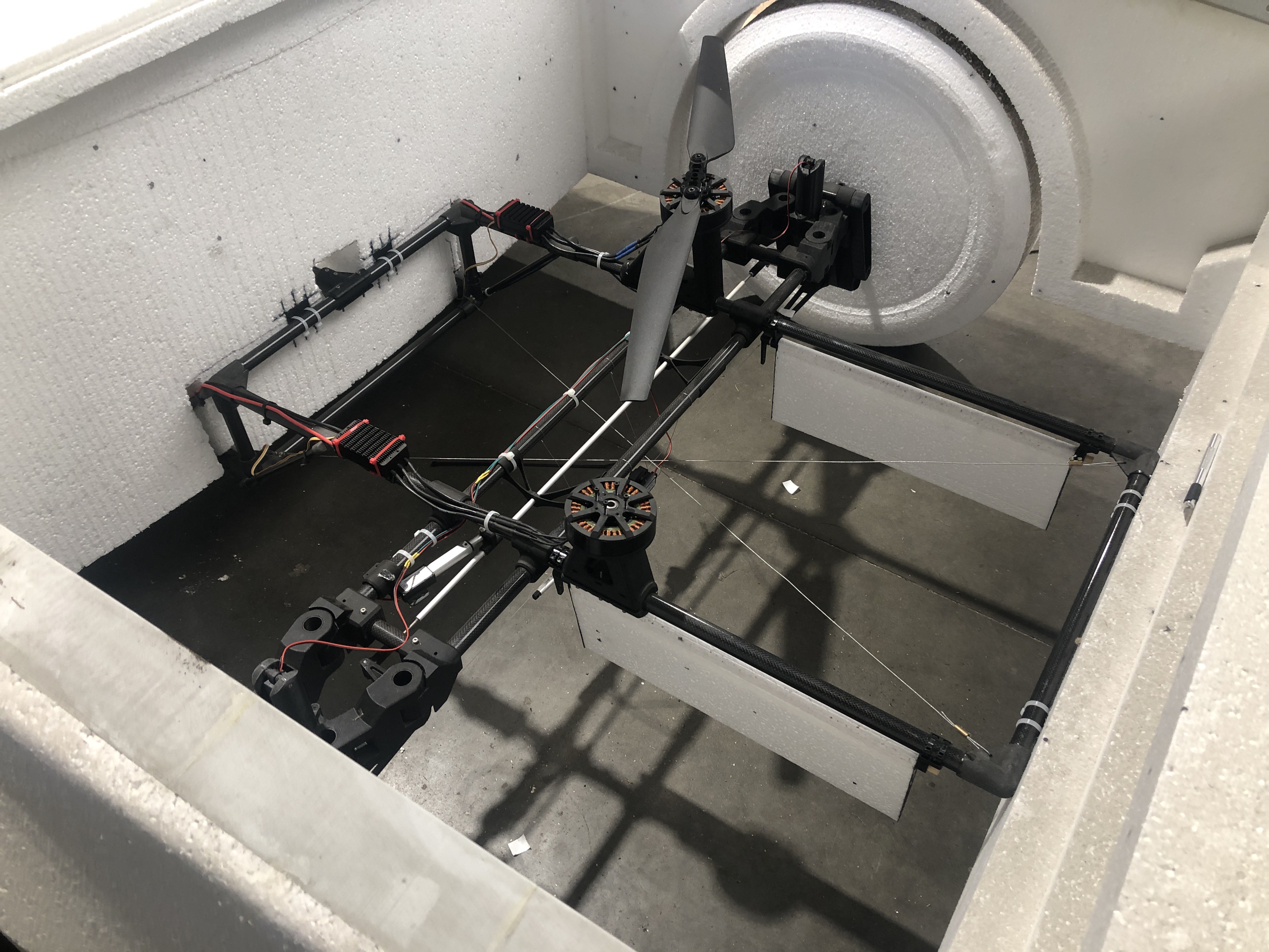
Thrust Vector Control (TVC) (yaw) flaps
After the foam EPS DeLorean body was placed on the drone, I noticed I had very little control over the yaw axis of the car. This resulted in a max yaw output of the flightcontroller where 2 of the 4 motors were at max throttle and the 2 others weren't doing that much. This made the car lower (fall) out of the air, because it was basically flying on 2 motors.
For this reason I decided to make some TVC fins (yaw flaps) that could better control the airflow under the propellers to guide them in the desired direction.
Because this is no standard option in the flight controller (a SpeedyBee F405 wing) and I'm unfamiliar with Luna scripting in the flightcontroller, I decided to copy the the output from the motors to 4 free channels of the flightcontroller. I then used an Arduino Nano to read these 4 channels and mix the output to the flaps so they only react to the desired yaw output (and not also roll output, I tried this but this made the Delorean oscilate). This ended up working great and gave me a lot more control authority over the yaw axis.
Second update of the project (01/07/2024)
(first update see further down)
This is the second part of the Full scale flying Delorean project where I finish up some mechanisms on the car like the front hood louvres and automatic doors. I also build an initial test frame for the drone out of some spare aluminium profiles I had lying around from a previous project. Second part video of the project can be found here:
Building the airframe
As mentioned above, I recently build an initial test frame for the drone out of some spare aluminium profiles I had lying around from a previous project. The frame is being held together by 3D-printed parts made from PLA plastic. Weighing in at around 8-9 kg this frame will probably to heavy to carry the Delorean body but it's main purpose is to function as a test base to see if this configuration could even fly and find some initial PID values.
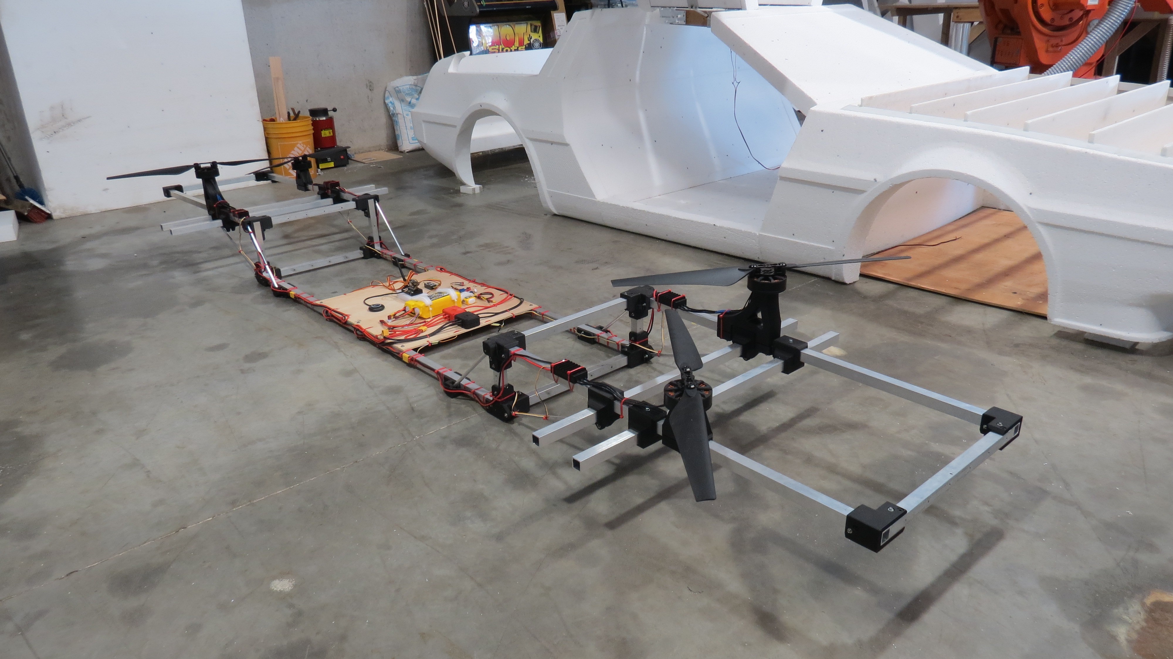
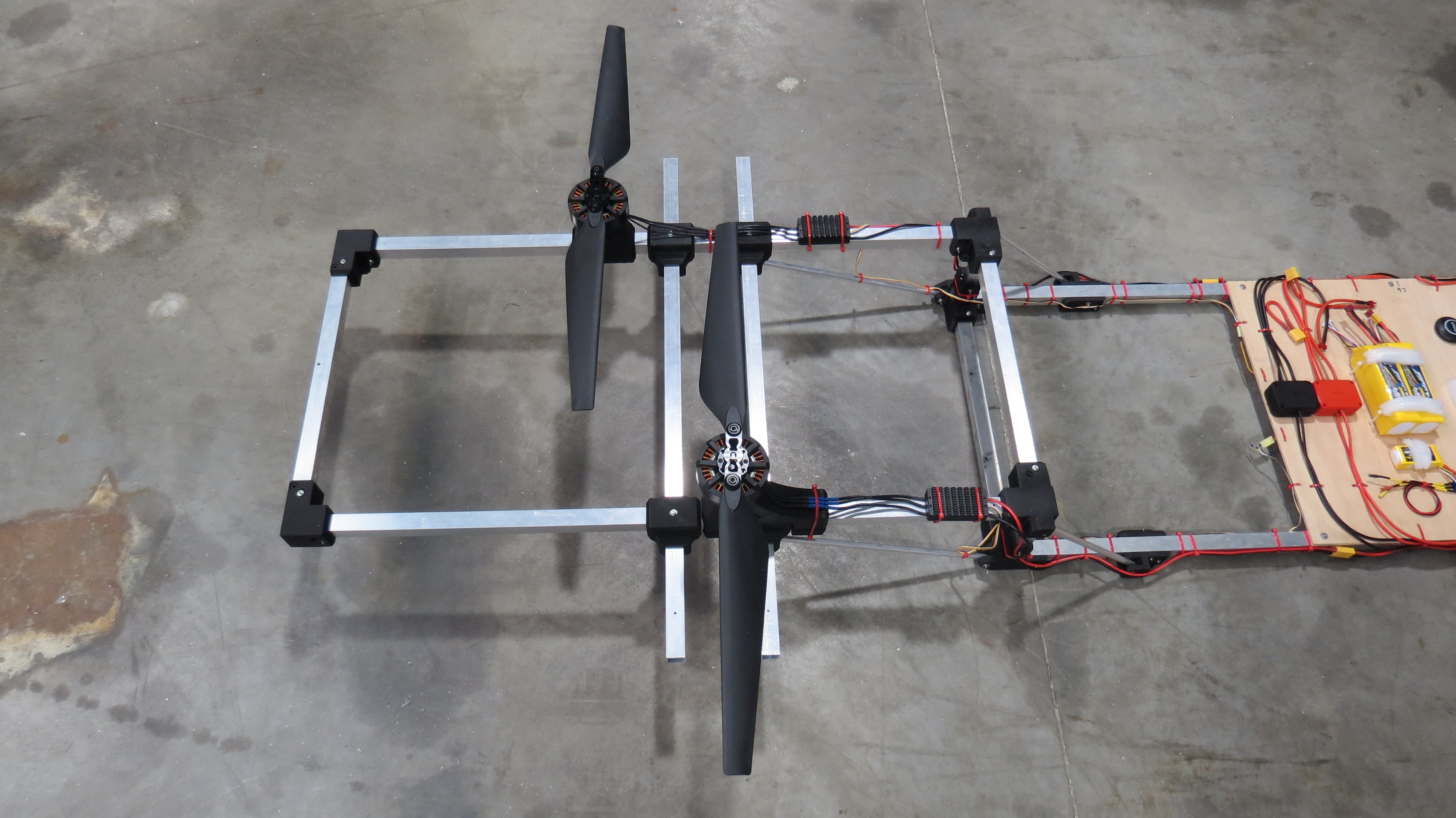
The motors itself are way overpowered to lift the frame on it's own with each motor capable of lifting around 14kg. The main issue of this initial frame is the flexibility of the aluminium. When trying to yaw left, the left front motor and right back motor will spin faster, twisting the front of the frame to the right and the back of the frame to the left, making the thrust of the 4 motors point in the opposite direction of the yaw motion that was intended. the weight and twist issues will probably be solved with the next frame made from carbon fiber. Estimated weight for this would be around 2kg.
How to make it fly?
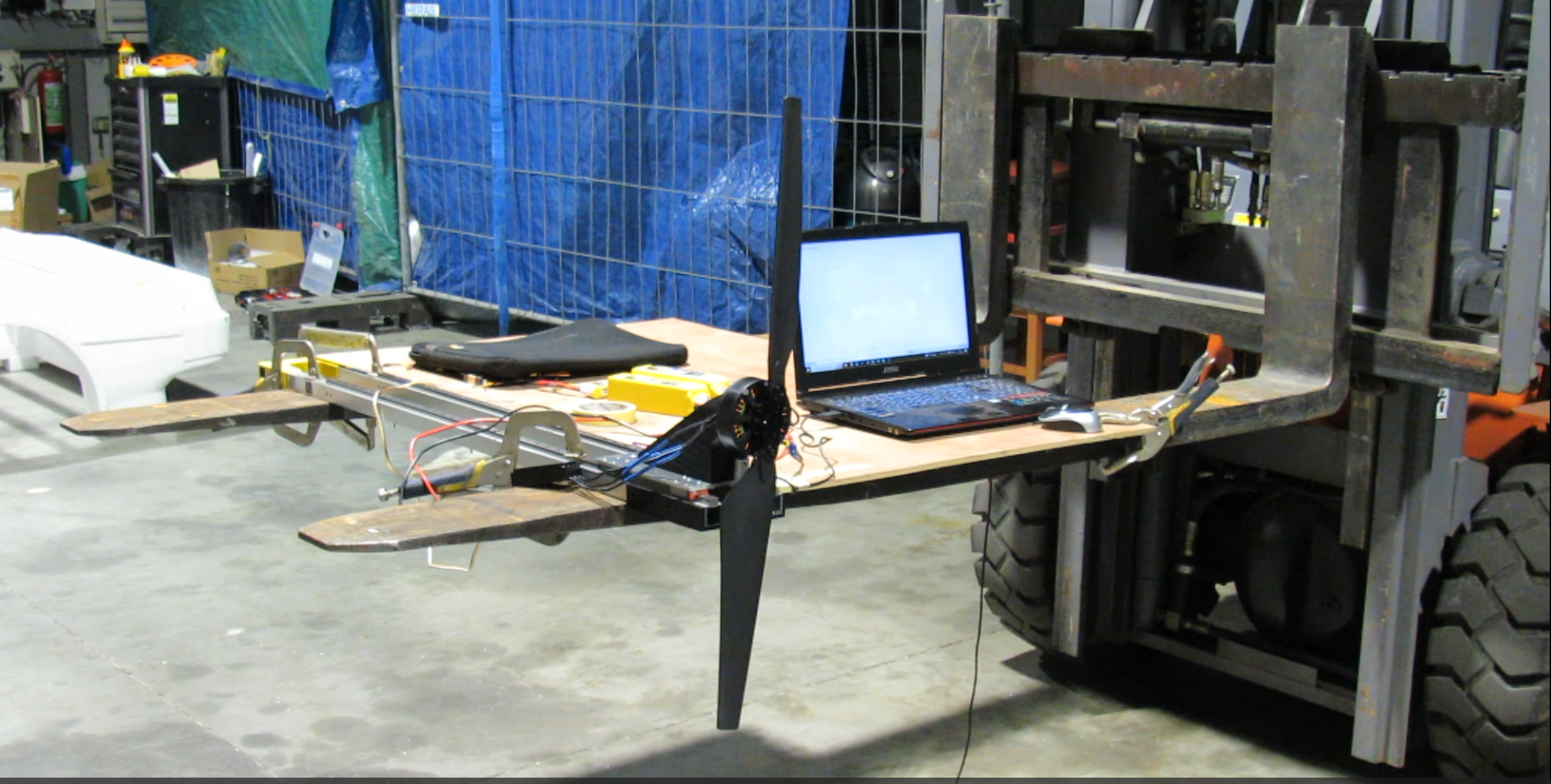
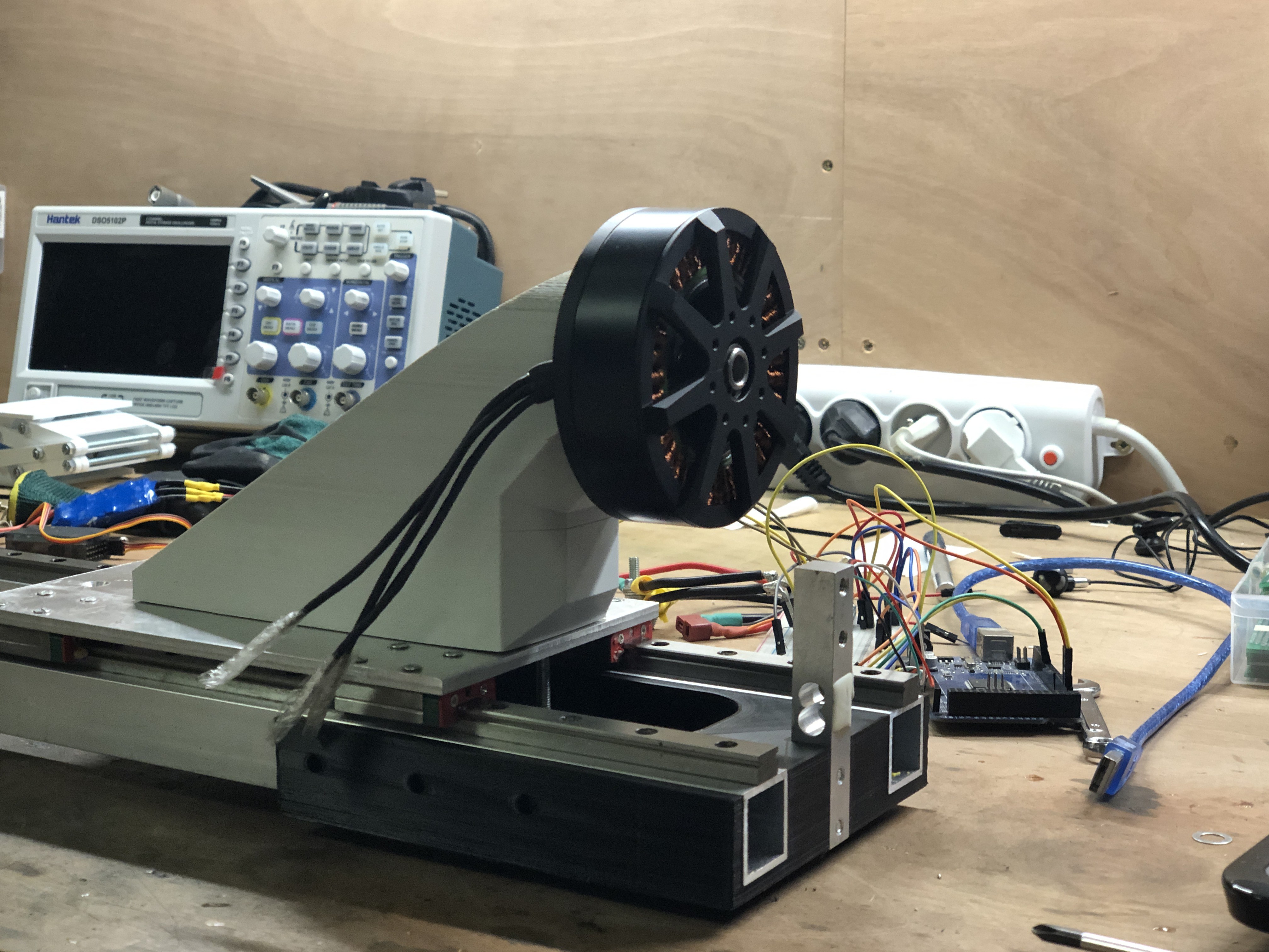
The original plan was to use 8 MP8318 100kv 3000W motors with each a 30 inch propeller to be on the safe side as I didn't know if the thrust numbers of the manufacturer of the motors were correct and what the final weight of the body would be. We now know the weight of the body is around 14kg and I ordered 1 motor to do some testing. The graph below shows the results of the test:
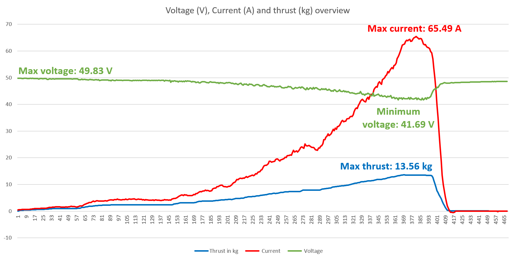
At 100% thrust we were able to achieve 13.563 kg of thrust which is more than the manufacturer of the motors advertised (12.5kg). The goal is to keep the takeoff weight at around 50% of the max thrust of the quadcopter which would be 4 x 13.5kg = 54kg * 50% = 27kg. which is almost twice the weight of the body currently. Worst case scenario we could go to 75% thrust takeof weight which would be 54kg x 75% = 40.5kg. If this would still not be enough, we go back to the original plan, I buy 4 more motors and make it an octocpter.
Here is an overview of the test stand. It uses an arduino nano, a 20kg Load cell to measure thrust, an ACS770 ECB-200B Bidirectional 200A hall-effect current sensor (which is really great for measuring higher currents reliably) and a simple voltage devider to measure voltage. The frame and linear rails were originally the Z-axis on a 5-axis cnc I build a while back but this project got replaced by my robot (In case you're interested: https://hackaday.io/project/181021-3d-printable-1x1x1m-5-axis-machine-3d-printer). I think i'll cover the build of this test stand in another article and the video of the test will be published in the next YouTube Video.
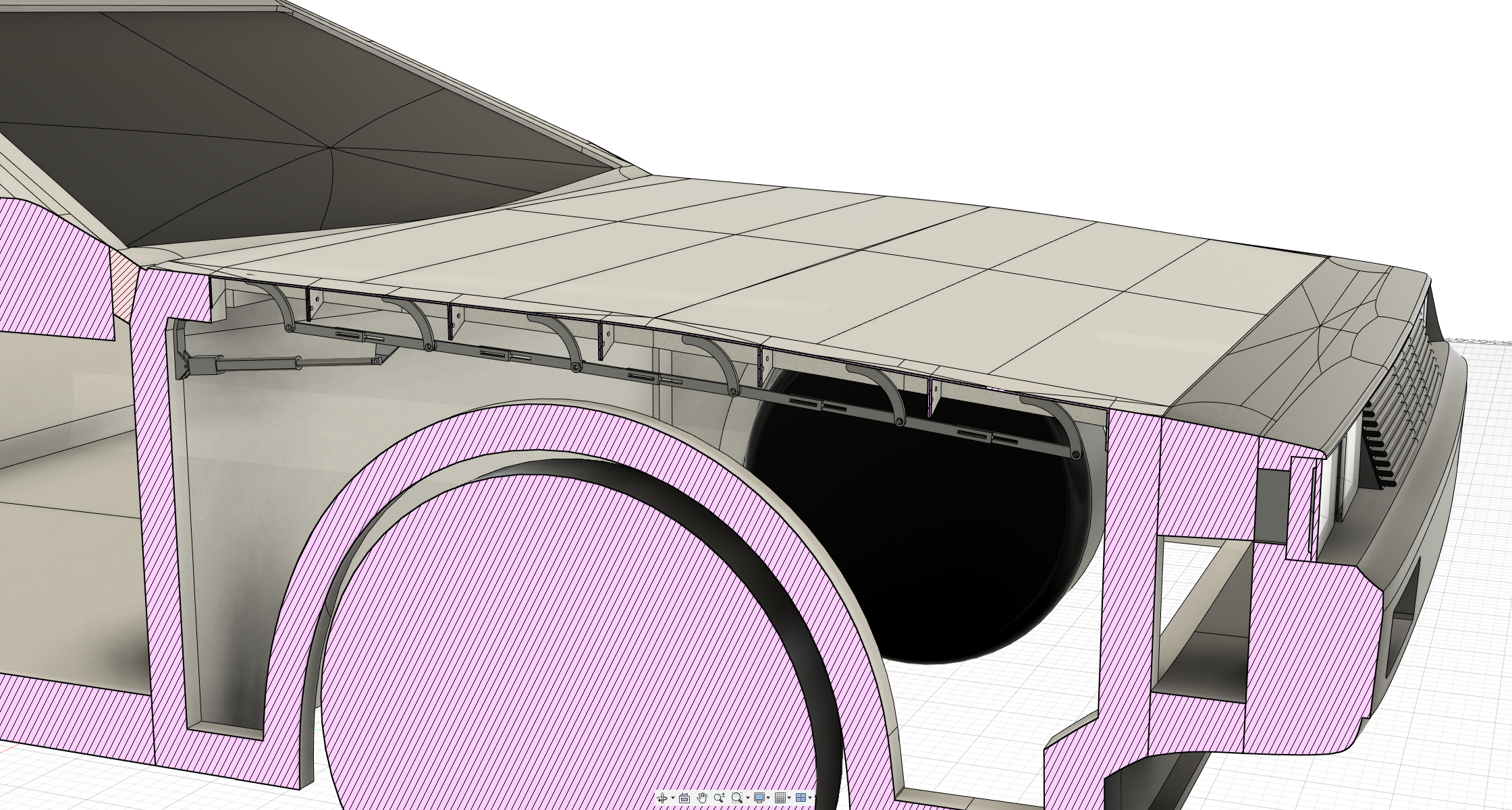
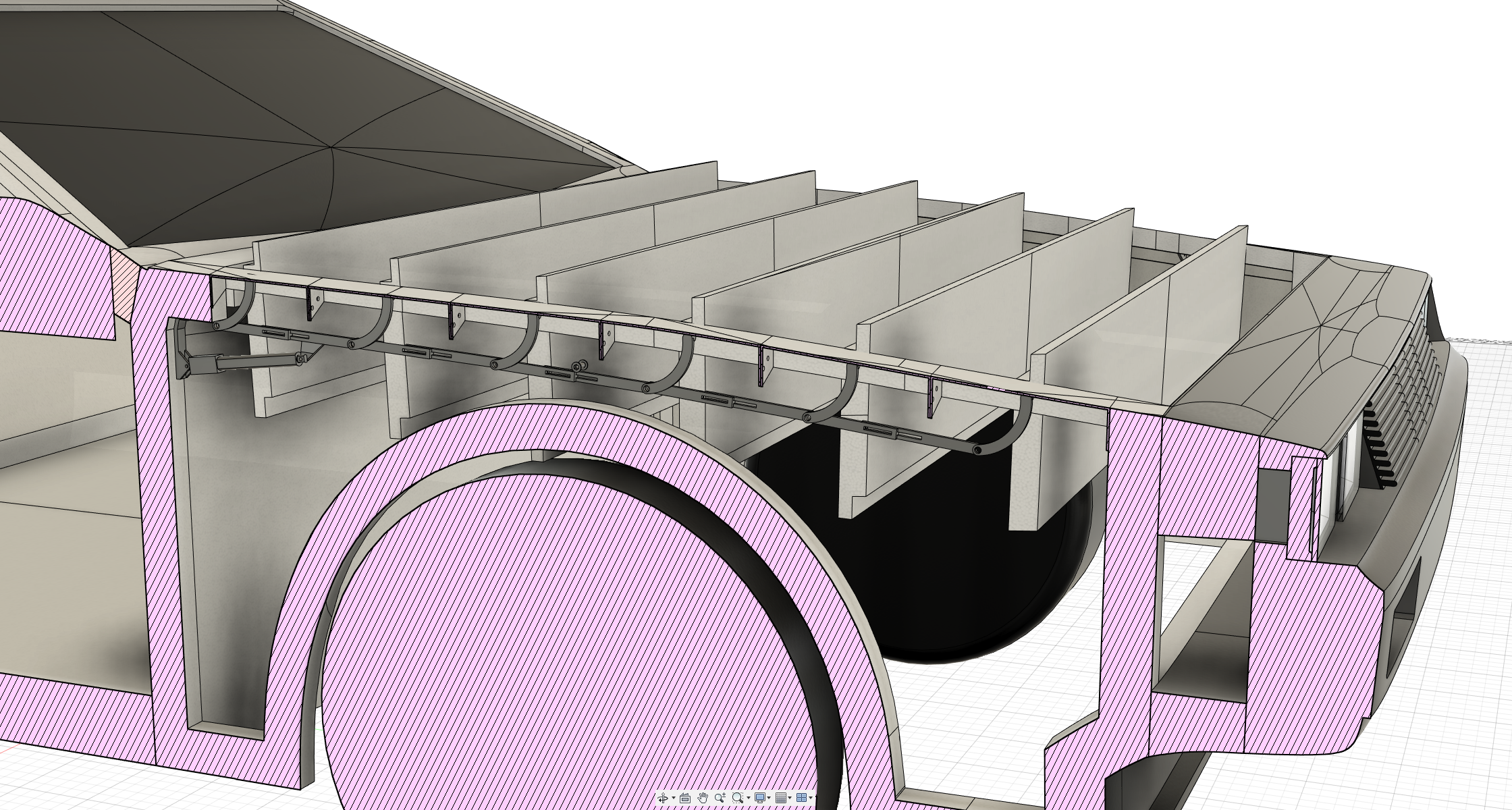
Hood flaps/slats/blades
To allow air to enter the propellers the front and back of the car needed to be hollow and the top needed to be open. This is all great but I didn't want 2 gaping holes in the front and the back so i made a flap-system connected to a linear actuator through mechanical linkages. This way the blades are conceiled when the flaps are closed and allow air to enter inside when they are open.
Automatic door hinge design
The automatic door hinge design for the gulwing doors was probably the most complicated design part of the whole build (so far). This is the part I spend the most time on. I didn't want the hinges to show on the roof of the car, I wanted an off-center hinge that's completely conceiled inside the roof and door itself, similar to real car doors.
In the picture below you can see the final design of the hinges. The hinges itself are 3D-printed and mounted onto 3mm thick MDF board covering almost the entire length of the roof. This ensure a solid base for the door. The EPS will later also be covered with fiberglass which will add some stiffness to the structure. A linear actuator is being used to push the doors open and closed. The linear actuators run on 12V, have a travel of 100mm and can push at a force of 150Nm. The doors are currently fully operational.
First update of the project
The first part of the project, the body of the Delorean, is complete and the properties closely match the properties of the 3D-model, The 3D-model has a calculated weight of 13.940kg and the real life model has a weight of 13.890kg, which is only of few grammes difference.
Build video can be found here:
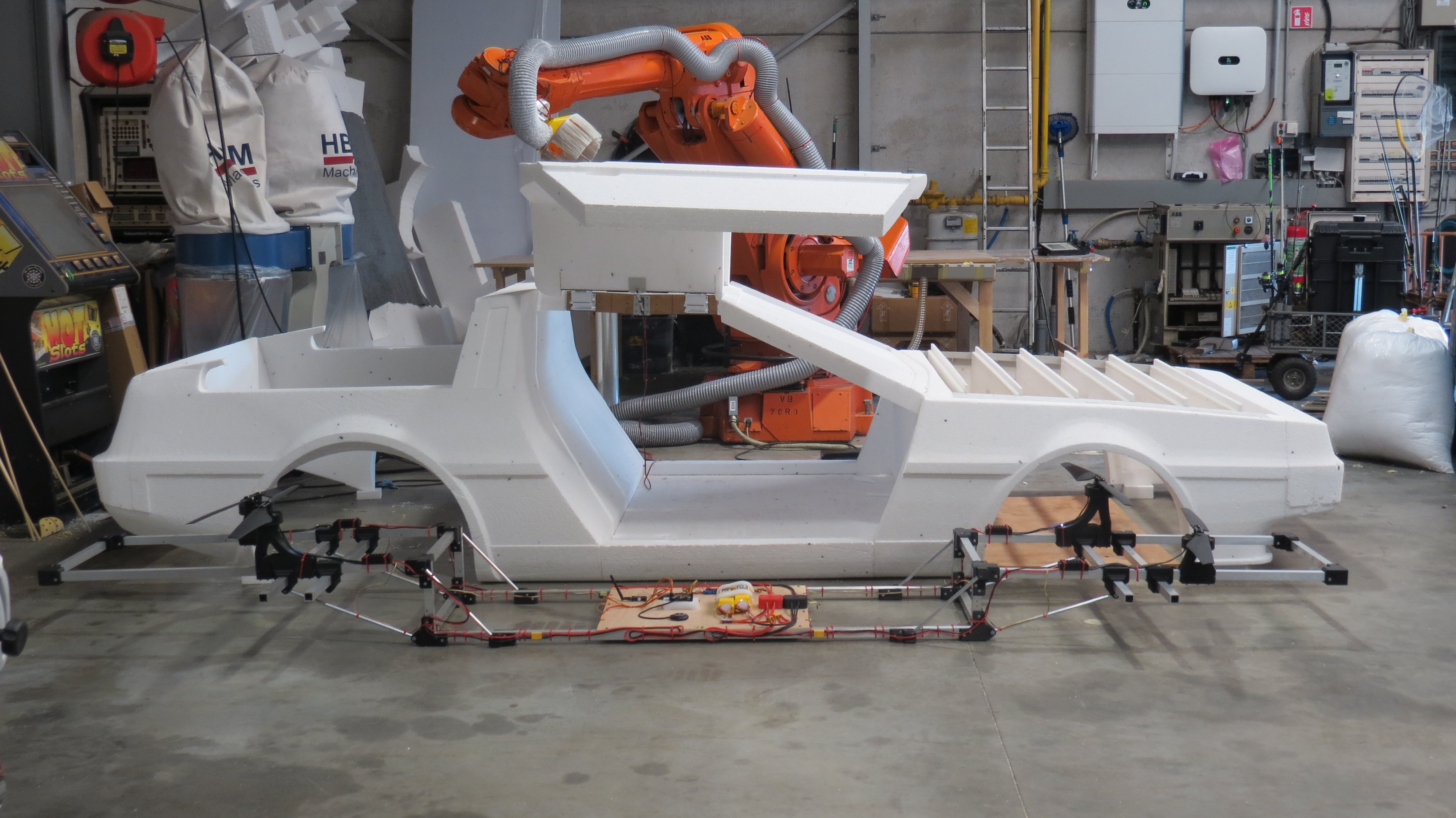
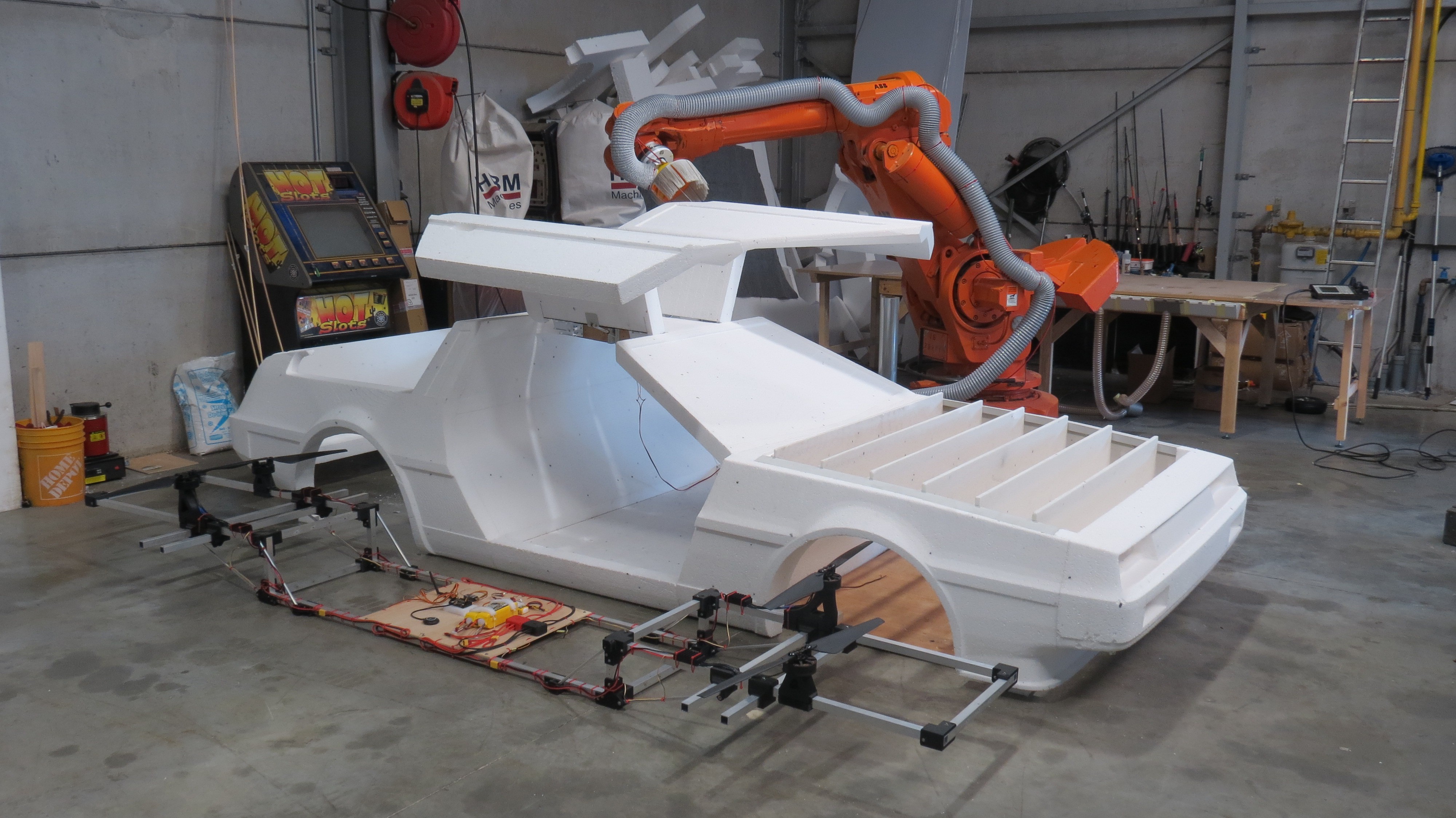
Building the main body
The Delorean model is designed using Fusion 360. I originaly wanted to use an existing model but editing mesh body's inside Fusion is not that great. So I had to design my own model. It's made using a lot of refference planes and photo's and using the exact dimensions of the real car. So it should be a pretty realistic model. I then had to devide the model into smaller slices that would fit on my CNC table. All parts were made by my ABB IRB6400 industrial robot which I resurected from the death in this project: https://hackaday.io/project/190511-turning-a-broken-2-ton-robot-into-a-cnc-machine
The front and back-end (also the middle part) is completely hollow to reduce weight and also to alow for air-flow, because yes it is supposed to fly. The hood consists out of individual slats/blades that will rotate open to alow for air-flow and closed to conceile the drone/rotor blades underneath
To give the Delorean some more durability, the EPS foam will be coverred in a layer of fiberglass with a weight of 25 gr/m² which is commonly used for RC-planes. The fiberglass will add a little bit structural integrity but it's main purpose is to protect the EPS foam. This will also alow the model to be painted as paint would currently dissolve the EPS-foam. The aluminium frame that wil be used to mount the motors on will also serve as support for the front and back end.