Delta belt 3D-printer for automated series production


DESCRIPTION
DETAILS
Video can be found here:
The Idea
I needed a way to print a lot small parts (cable chain pieces) fast and preferably in an automated way, so I build this modular delta belt 3D-printer for (small) automated series productions. It combines the best of both worlds, the speed of the delta printer and the automation of the conveyor belt.
Design
This design is mainly focused on series production (print a lot of parts in an automated way) and not so much on continuous printing (print very long pieces). The main reason for this is that for continuous printing the head needs to be tilted 45 degrees, which requires a lot of hardware changes to be made to the printer itself. With this design you need to make exactly 0 changes to the hardware and even the firmware of the printer (FLsun Q5 in my case). The belt is designed to be completely modular.
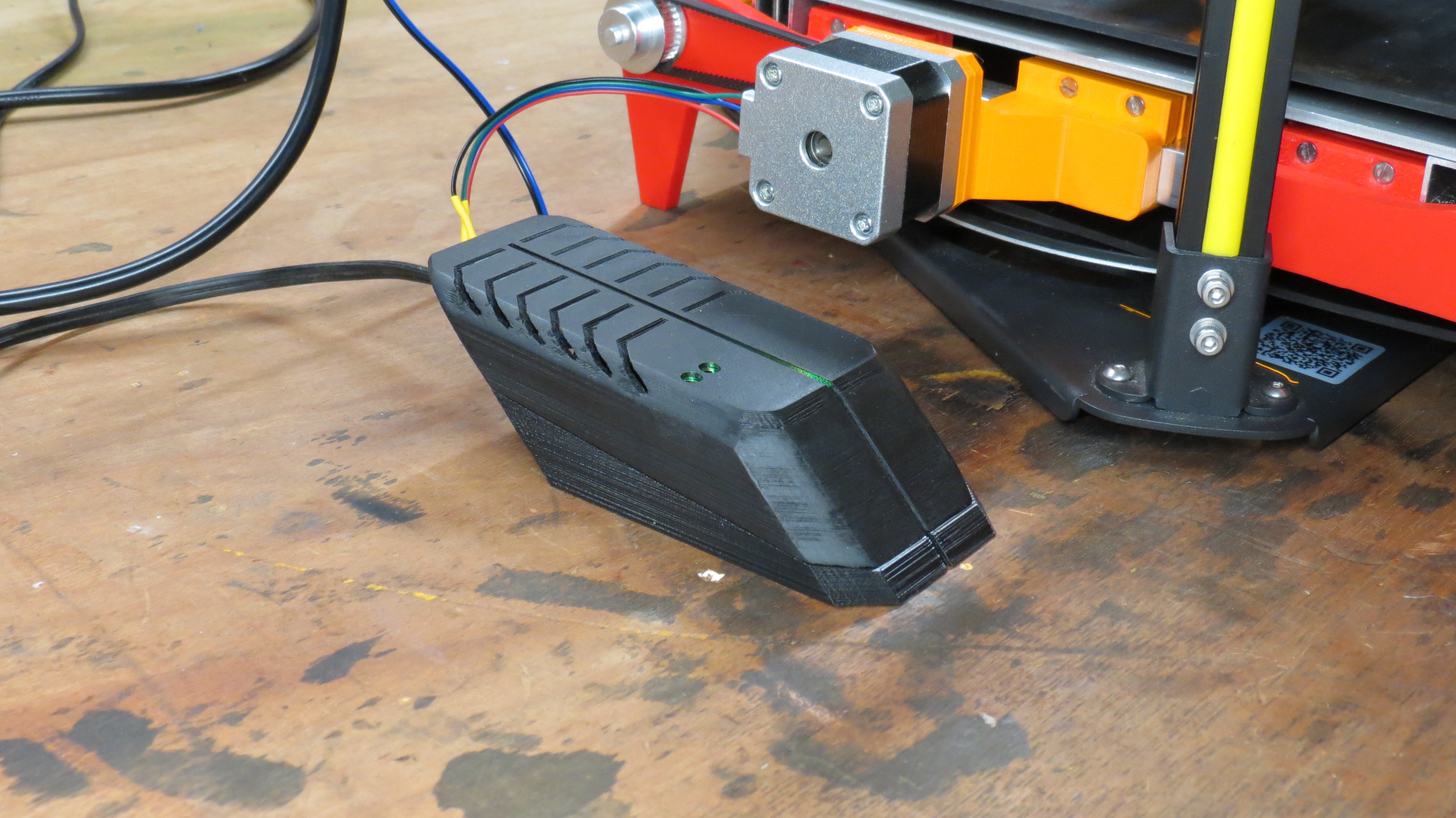
The belt is triggered by a limit switch which in turn is triggered by the homing sequence of the printer itself. The amount of parts you want to print can be chosen by copying and pasting the G-code the amount of times you want the part to print. I tried using some for loops in the G-code but the firmware of the FLsun Q5 doesn't seem to accept these codes.
The motor used to drive the belt is a 42mm 12V Nema 17 stepper motor. the stepper motor itself is driven by a A4998 stepper motor driver (see the parts list for a complete overview). To connect the motor with the roller shaft I used a 36 teeth GT2 pulley on the roller shaft, a 16 teeth GT2 pulley on the motor shaft and a 260mm GT2 belt to connect them both.
PCB design
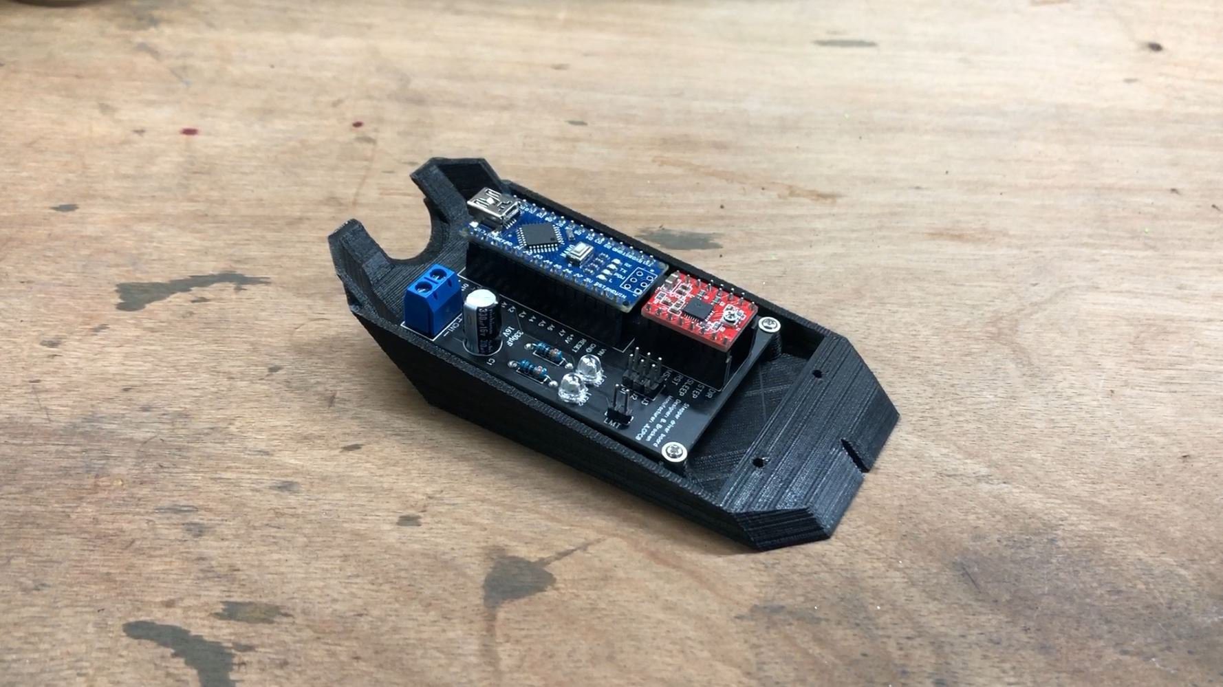
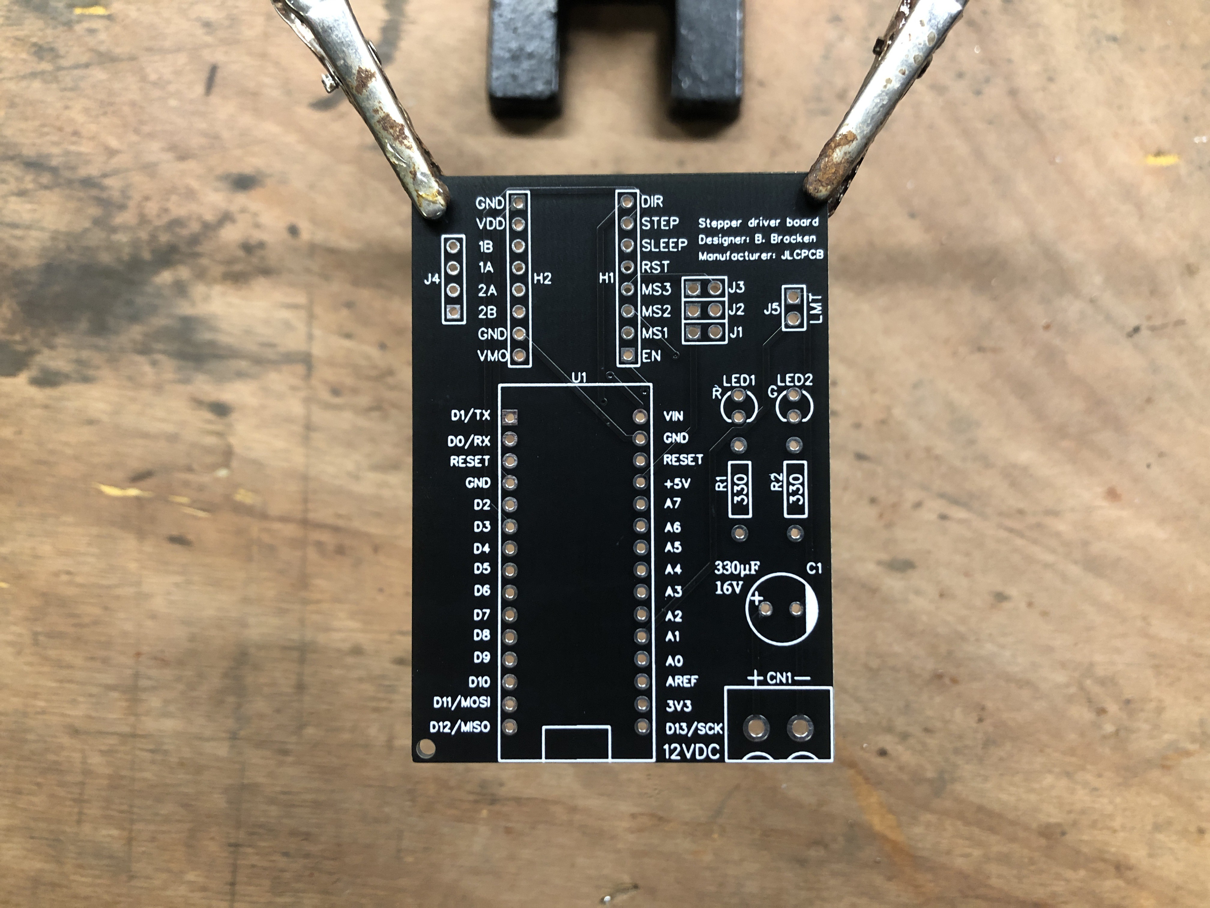
I decided to create a small Arduino based PCB which was manufactured by JLCPCB, the sponsor of this project. The gerber files and Arduino code can be found in the files section of this project page.
I used an Arduino Nano to read the input from the limit switch and to control the stepper motor through the A4998 stepper motor driver. Also included on the PCB are 2 status LEDs with appropriate resistors. Next to the stepper motor driver are some pins (J1, J2, J3) to select the microstepping of the driver. Pins J4 go to the stepper motor. C1 is a capacitor to smooth out the power going to the Arduino power supply.

PCB case
To protect the PCB a bit I wanted to create a case around it. I started to design a square box like I usually would but thought it looked so boring. So i decided to put some time and effort in the design of the case and took some inspiration from Lamborghini to give it a modern and futuristic look. I personally like how the design turned out.
Belt design
For the conveyor belt itself I used a rubber sheet of about 3mm thickness and cut it to 200x666mm. I first tested out which glue had the best performance, here are the numbers:
-Pattex contact glue: 13 kg
-Bison super glue: 22 kg
-Bison rubber repair: 24+ kg
I ended up using the Bison rubber repair glue and glued both ends of the rubber sheet to each other end-to-end.
The main reason i went with 3mm thick rubber is the possibility to glue the rubber end to end so there's no seem. I did some tests with 1mm rubber sheet, with this one an overlap was necessary. 3mm rubber is also less prone to warping on the sides then the 1mm rubber. The thermal conductivity of the 1mm rubber sheet is better than the one of the 3mm sheet.
I did some testing on the thermal conductivity of the 3mm sheet. When using a heated bed which is heated to 40 degrees, the top of the rubber sheet is about 8 degrees lower (test was performed with a thin sheet of wood underneath, used as a base where the rubber was glued on to, I'll have to do aditional testing with the rubber sheet directly on to the heated bed). Thermal images of the tests can be seen below.


Printer used:
Flsun Super Racer
Supports:
Yes
Resolution:
0.20
Infill:
25-30%
FILES
STL-files and the Fusion 360 source files can be downloaded here: https://bbprojects.technology/collections/stl-fusion-360-source-files/products/delta-belt-3d-printer
Arduino code can be downloaded here.
PCB gerber file can be downloaded here.
COMPONENTS
PROJECT LOGS
-
Arduino code has been added to the files
// Defines pins numbers const int stepPin = 3; const int dirPin = 4; const int Enable = 5; const int GLED = 6; const int RLED = 7; const int LmtSwtch = A1; const int Mspeed = 500; //delay between pulses to determine the motor speed (smaller delay = faster motor) int Lastbuttonstate = 1; int flag1 = 0; int StepAmount = 0; int StepAmountSet = 6000; //Amount of steps that have to be taken (distance the belt travels when switch is triggered) int customDelay,customDelayMapped; // Defines variables void setup() { // Sets the pins as outputs pinMode(stepPin,OUTPUT); pinMode(dirPin,OUTPUT); pinMode(Enable, OUTPUT); pinMode(LmtSwtch, INPUT_PULLUP); pinMode(GLED, OUTPUT); pinMode(RLED, OUTPUT); //Serial.begin(115200); //uncomment line to use serial monitor digitalWrite(dirPin,HIGH); //Enables the motor to move in a particular direction digitalWrite(RLED,HIGH); digitalWrite(GLED,HIGH); } void loop() { int Buttonstate = digitalRead(LmtSwtch); if (Buttonstate < Lastbuttonstate){ flag1 = 1; } Lastbuttonstate = Buttonstate; if (flag1 == 0) { digitalWrite(Enable, LOW); digitalWrite(stepPin, LOW); } if (flag1 == 1 && StepAmount < StepAmountSet) { digitalWrite(Enable, LOW); digitalWrite(stepPin, HIGH); delayMicroseconds(Mspeed); digitalWrite(stepPin, LOW); delayMicroseconds(Mspeed); StepAmount = StepAmount + 1; } else { flag1 = 0; StepAmount = 0; } /* Serial.print("Buttonstate: "); //uncomment this section to use serial monitor Serial.print(Buttonstate); Serial.print(" flag1: "); Serial.print(flag1); Serial.print(" StepAmount: "); Serial.println(StepAmount); */ } -
PCB Gerber files has been added to the files
Hello @Roberto you have some very interesting questions, i incorporated your questions in the section about the belt in the article.
I have looked at your design and i think it is indeed really great for series production.
Smart using a homeing endstop switch to trigger the move, klipper users can just add the arduino as extra mcu and trigger the change internally, see the docs.
What i was thinking though, using rubber of 3mm, is the heated bed going to heat the rubber well enough, i found rubber has a poor thermal conductivity, but it contracts when heated. So you might be better of in terms of heat conductance with using 1-2mm rubber sheet, but it might start to contract a bit too much and degrade the glued stitch. What is your experience with the bed, can you stably get it at 65 degree (the rubber)? And would you think a thinner belt would be possible? Or do you have other reasons for the 3mm?
Thanks in advance,
Greets